Week 2 – Arduino analog input & digital output
This week’s project was an absolute rollercoaster. I came up with my idea quickly: I wanted to combine a variable resistor potentiometer with 2-3 multi-color LEDs, allowing the user to rotate the dial & change the hue of a tiny lamp, preferably complete with a home-brew lampshade.
After initial setup issues, I completed the lab fine with my MacBook & Arduino, but once I sat down to work on my project, the Arduino would no longer be recognized by the Mac whatsoever. It wasn’t an issue with the IDEs—I tried both versions—the macOS System Report wasn’t recognizing any devices plugged in via USB when the Arduino was connected. I tried multiple different USB cables, USB hubs, & I knew they were working fine since other micro-USB devices worked fine. I updated & restarted my MacBook Pro multiple times. I reset the Arduino. I crossed my fingers. Finally, after a few emails with Professor Song, she suggested my circuit could be shorting, which prevents the Arduino from showing up. Incredible! Your Arduino won’t mount as a USB device while on a short circuit. Took me a few days to learn, but now I know, & now you know.
Since I didn’t arrive at this wonderful advice until Monday, the timeline for the rest of the project was stressedly compressed, but I finally did build what I was hoping for.
Along the way, the short circuit from my first prototype fried the LEDs on my board, which caught up with me later as I started working & was confused why the properly-wired LED didn’t illuminate. “Always something” when it comes to building electronics.
The build
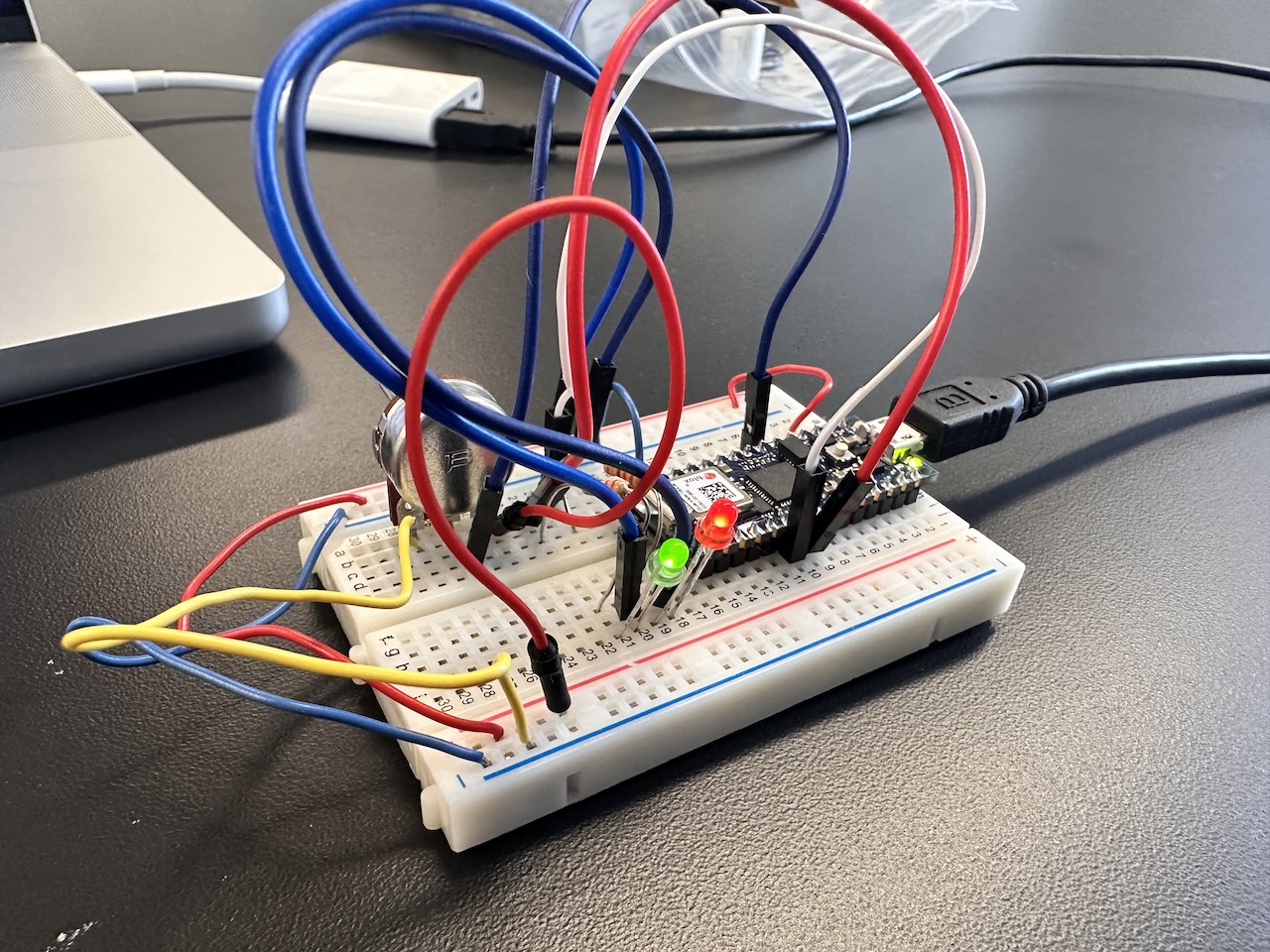
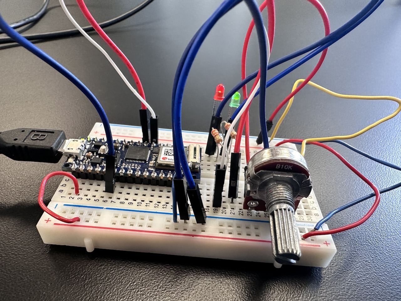
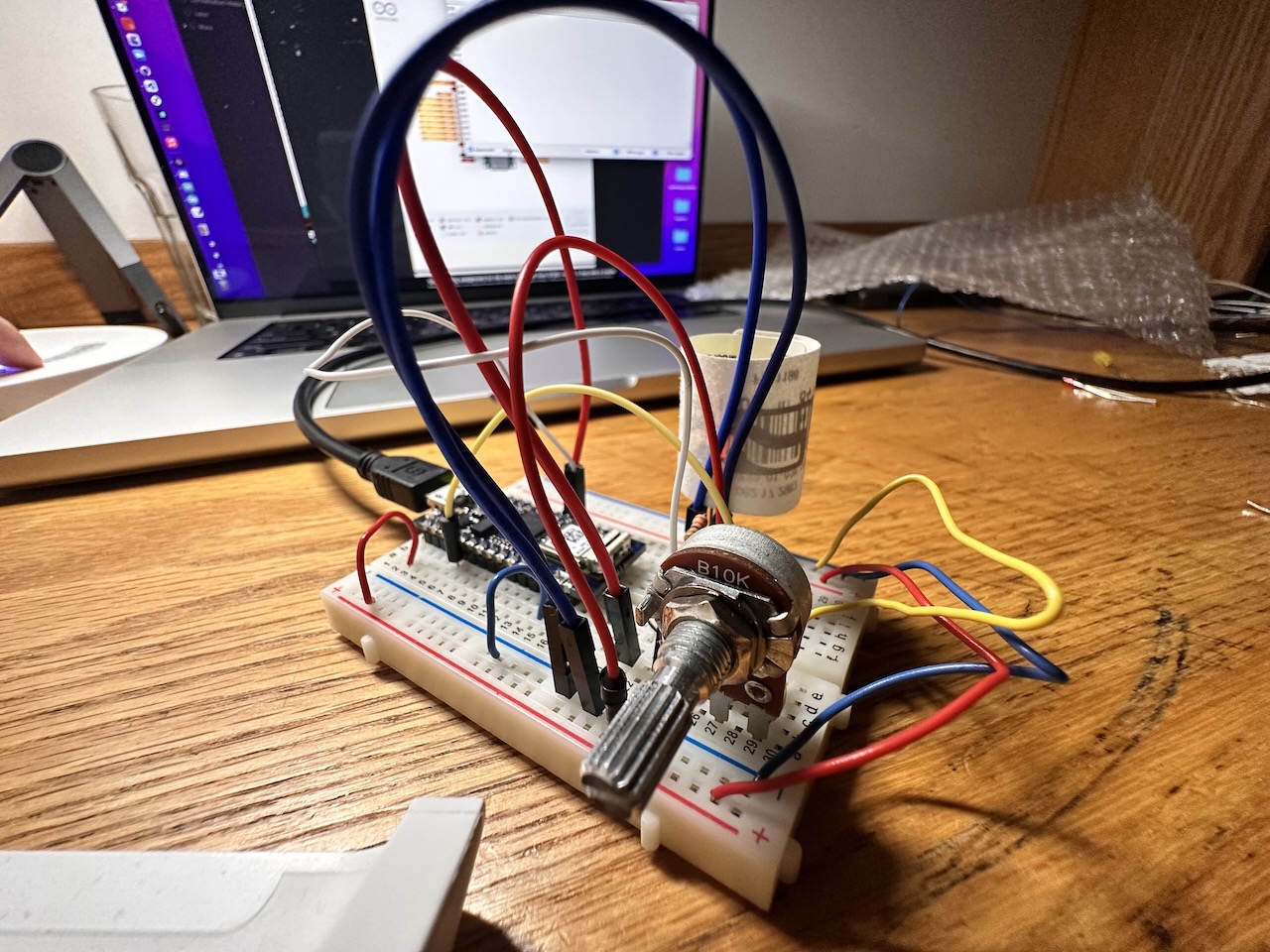
The project includes the Arduino on the breadboard, then three circuits: one for the potentiometer, one for the variable-brightness red LED, one for the variable-brightness green LED. If I had more stripped wires & time I’d have added a third, blue LED.
Following a tip from Priyanka, I found a similar component to the potentiometer I acquired by now-forgotten means in 2019 via Google Images, which included this handy reference on the 3 pins:
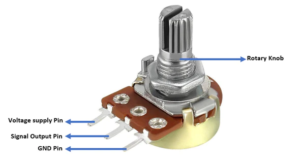
I initially was connecting the power & ground directly to those pins on the Arduino, before making the mental connection that. That’s perhaps what I’m proudest of this week, more than the project itself: markedly improving my internal understanding of the basics of circuits. Before executing this project I didn’t truly understand power/ground, the side rails, whether cables could carry power & data, the two legs of the LED, when circuits would short, or what the different regions of Arduino pins would do; between trial & error personal discoveries & talking through mental models with Professor Song, I feel like I’ve got basics down, which I was hoping would happen.
The LED circuits were straightforward to implement, consisting each of a cable connecting to a digital output on the Arduino, a power cable, a resistor, the LED, & a ground cable. Using the resistors as wires that happened to do the voltage transformation I was looking for removed one wire from each circuit.
To model the relationship between the dial & LED brightness values:
- The dial provides analog input,
0to1023. - The LEDs require inputs of
0to255for brightness. - The different colors of LED should have an inverse relationship. At one
255, the other should be0; subtracting one from255calculates this.
My final code I found straightforward to implement:
const int redLedPin = 3;const int greenLedPin = 4;int dialValue = 0;int redBrightness = 0;int greenBrightness = 0;void setup() {Serial.begin(9600);pinMode(redLedPin, OUTPUT);pinMode(greenLedPin, OUTPUT);}void loop() {dialValue = analogRead(A2);redBrightness = dialValue / 5; // fit in a byte: 0-(1023/4) => 0-255greenBrightness = 255 - redBrightness;analogWrite(redLedPin, redBrightness);analogWrite(greenLedPin, greenBrightness);Serial.println(redBrightness);}
(Adding a blue LED would add complexity to the arithmetic, but would split the difference between the two extra LEDs instead of subtracting everything on the green.)
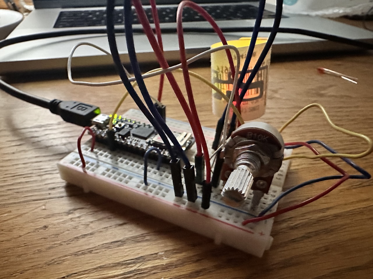
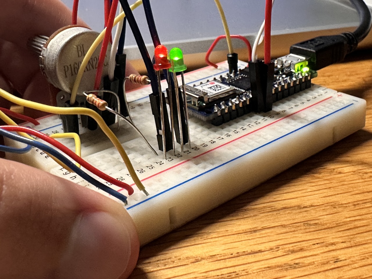
At the final moment, the circuits worked beautifully, & I modeled an impromptu lampshade out of a sticker folded in on itself. After excitedly playing with the dial & testing lampshade designs, while setting up my iPhone to take a video, somehow the dial stopped working. What my iPhone setup & moving the board had to do with this, I do not know. I entirely removed the dial & its wiring, set it back up on a fresh port with different wires, but I can’t figure out what I broke. Unfortunately I don’t have the video demo I was truly excited for, but here’s stills instead.
Two steps forward, one step back. Even if I don’t have a functioning demo to show off, it did work at one point, & I’ve got fundamental mental models, so this week was a win.
Update: 2022-09-20
After getting my build checked out with a multimeter, it turned out the project stopped working because the signal wire from the potentiometer flat-out failed. The joys of physical objects!
The final product: